Windows提供了各种在设备上下文中使用的绘图工具.它提供了用于绘制线条的笔,用于填充内部的笔刷以及用于绘制文本的字体. MFC提供与Windows中的绘图工具等效的图形对象类.
设备上下文是一个Windows数据结构,包含有关绘图的信息设备的属性,例如显示器或打印机.所有绘图调用都是通过设备上下文对象进行的,该对象封装了用于绘制线条,形状和文本的Windows API.
设备上下文允许在Windows中进行与设备无关的绘图.设备上下文可用于绘制到屏幕,打印机或图元文件.
CDC 是在MFC中绘制的最基本的类. CDC对象提供执行基本绘图步骤的成员函数,以及用于处理与窗口的客户区域相关联的显示上下文的成员.
| Sr.不. | 姓名&说明 |
|---|---|
| 1 | AbortDoc 终止当前的打印作业,删除自上次调用 StartDoc 成员函数以来应用程序写入设备的所有内容. |
| 2 | AbortPath 关闭并丢弃设备上下文中的任何路径. |
| 3 | AddMetaFileComment 将缓冲区中的注释复制到指定的增强格式元文件中. |
| 4 | AlphaBlend 显示具有透明或半透明像素的位图. |
| 5 | AngleArc 绘制线段和圆弧,并将当前位置移动到结束点弧. |
| 6 | Arc 绘制一个椭圆箭头c. |
| 7 | ArcTo 绘制椭圆弧.此功能类似于Arc,但当前位置已更新. |
| 8 | Attach 将Windows设备上下文附加到此CDC对象. |
| 9 | BeginPath 在设备上下文中打开路径括号. |
| 10 | BitBlt 从指定的设备上下文复制位图. |
| 11 | Chord 抽奖和弦(由椭圆和线段的交点限定的闭合数字). |
| 12 | CloseFigure 关闭路径中的空心数字. |
| 13 | CreateCompatibleDC 创建与其他设备上下文兼容的内存设备上下文.您可以使用它在内存中准备图像. |
| 14 | CreateDC 为特定设备创建设备上下文. |
| 15 | CreateIC 创建信息特定设备的上下文.这提供了一种快速获取设备信息的方法,而无需创建设备上下文. |
| 16 | DeleteDC 删除与此CDC对象关联的Windows设备上下文. |
| 17 | DeleteTempMap 由 CWinApp 空闲时间处理程序调用,以删除由FromHandle创建的任何临时CDC对象.同时分离设备上下文. |
| 18 | Detach 从此CDC对象中分离Windows设备上下文. |
| 19 | DPtoHIMETRIC 将设备单位转换为 HIMETRIC 单位. |
| 20 | DPtoLP 将设备单位转换为逻辑单位. |
| 21 | Draw3dRect 绘制一个三维矩形. |
| 22 | DrawDragRect 在拖动矩形时擦除并重绘. |
| 23 | DrawEdge 绘制矩形的边缘. |
| 24 | DrawEscape 访问不能直接使用的视频显示的绘图功能h图形设备接口(GDI). |
| 25 | DrawFocusRect 在用于指示焦点的样式中绘制一个矩形. |
| 26 | DrawFrameControl 画一个帧控制. |
| 27 | DrawIcon 绘制一个图标. |
| 28 | DrawState 显示图像并应用视觉效果来指示状态. |
| 29 | DrawText 在指定的矩形中绘制格式化文本. |
| 30 | DrawTextEx 使用其他格式在指定的矩形中绘制格式化文本. |
| 31 | Ellipse 绘制一个椭圆. |
| 32 | EndDoc 结束由StartDoc成员函数启动的打印作业. |
| 33 | EndPage 通知设备驱动程序页面正在结束. |
| 34 | EndPath 关闭路径括号并选择括号定义到设备上下文中的路径. |
| 35 | EnumObjects 枚举钢笔和画笔在设备上下文中可用. |
| 36 | ExcludeClipRect 允许应用程序访问通过GDI无法从特定设备直接获得的设施.还允许访问Windows转义功能.应用程序进行的转义调用将被转换并发送到设备驱动程序. |
| 37 | ExcludeClipRect 创建一个新的剪裁区域,该区域由现有剪辑区域减去指定的矩形组成. |
| 38 | ExcludeUpdateRgn 通过从剪切区域中排除窗口中的更新区域,防止在窗口的无效区域内进行绘制. |
| 39 | ExtFloodFill 使用当前画笔填充区域.提供比 FloodFill 成员函数更多的灵活性. |
| 40 | ExtTextOut 使用当前选定的字体在矩形区域内写入字符串. |
| 41 | FillPath 关闭当前路径中的所有打开数字,并使用当前画笔和多边形填充模式填充路径内部. |
| 42 | FillRect 使用特定画笔填充给定的矩形. |
| 43 | FillRgn 使用指定画笔填充特定区域. |
| 44 | FillSolidRect 用纯色填充矩形. |
| 45 | FlattenPath 将选定路径中的任何曲线转换为curr设备上下文,并将每条曲线转换为一系列行. |
| 46 | FloodFill 使用当前画笔填充区域. |
| 47 | FrameRect 在矩形周围绘制边框. |
| 48 | FrameRgn 使用画笔在特定区域周围绘制边框. |
| 49 | FromHandle 返回指向给定设备上下文句柄时的CDC对象.如果CDC对象未附加到句柄,则会创建并附加临时CDC对象. |
| 50 | GetArcDirection 返回设备上下文的当前弧方向. |
| 51 | GetAspectRatioFilter 检索当前宽高比滤波器的设置. |
| 52 | GetBkColor 检索当前背景颜色. |
| 53 | GetBkMode 检索背景模式. |
| 54 | GetBoundsRect 返回指定设备上下文的当前累积边界矩形. |
| 55 | GetBrushOrg 检索当前刷子的来源. |
56 | GetCharABCWidths 检索给定连续字符的宽度(以逻辑单位表示)范围从当前字体. |
| 57 | GetCharABCWidthsI 从当前TrueType字体中检索指定范围内连续字形索引的宽度(以逻辑单位表示.) |
| 58 | GetCharacterPlacement 检索字符串的各种类型的信息. |
| 59 | GetCharWidth 从当前字体中检索给定范围内连续字符的小数宽度. |
| 60 | GetCharWidthI 以逻辑坐标检索当前字体指定范围内的连续字形索引的宽度. |
| 61 | GetClipBox 检索当前剪裁边界周围最紧的边界矩形的尺寸. |
| 62 | GetColorAdjustment 检索颜色调整值设备上下文. |
| 63 | GetCurrentBitmap 返回指向当前所选 CBitmap 对象的指针. |
| 64 | GetCurrentBrush 返回指向当前所选 |
| 65 | GetCurrentFont 返回指向当前所选 CFont 对象的指针. |
| 66 | GetCurrentPalette 返回指向当前所选 CPalette 对象的指针. |
| 48 | GetCurrentPen 返回指向当前所选 CPen 对象的指针. |
| 67 | GetCurrentPosition 检索笔的当前位置(在逻辑坐标中) . |
| 68 | GetDCBrushColor 检索当前画笔颜色. |
| 69 | GetDCPenColor 检索当前的笔颜色. |
| 70 | GetDeviceCaps 检索有关给定显示设备功能的指定类型的设备特定信息. |
| 71 | GetFontData 从可缩放字体文件中检索字体度量信息.通过指定字体文件中的偏移量和要返回的信息的长度来识别要检索的信息. |
| 72 | GetFontLanguageInfo 返回有关指定显示上下文的当前所选字体的信息. |
| 73 | GetGlyphOutline 检索当前字体中轮廓字符的轮廓曲线或位图. |
| 74 | GetGraphicsMode 检索当前的图形模式指定的设备上下文. |
| 75 | GetHalftoneBrush 检索半色调画笔. |
| 76 | GetKerningPairs 检索当前所选字体的字符字距调整对指定的设备上下文. |
| 77 | GetLayout 检索设备上下文(DC)的布局.布局可以是从左到右(默认)或从右到左(镜像). |
| 78 | GetMapMode 检索当前的映射模式. |
| 79 | GetMiterLimit 返回设备上下文的斜接限制. |
| 80 | GetNearestColor 检索指定设备可以表示的指定逻辑颜色的最接近的逻辑颜色. |
| 81 | GetOutlineTextMetrics 检索TrueType字体的字体度量信息. |
| 82 | GetOutputCharWidth 使用输出设备上下文从当前字体中检索连续字符组中各个字符的宽度. |
| 83 | GetOutputT abbedTextExtent 计算输出设备上下文中字符串的宽度和高度. |
| 84 | GetOutputTextExtent 计算宽度和高度使用当前字体确定尺寸的输出设备上下文中的一行文本. |
| 85 | GetOutputTextMetrics 从输出设备上下文中检索当前字体的指标. |
| 86 | GetPath 检索定义行的端点的坐标和在设备上下文中选择的路径中找到的曲线的控制点. |
| 87 | GetPixel 检索指定点处像素的RGB颜色值. |
| 88 | GetPolyFillMode 检索当前的多边形填充模式. |
| 89 | GetROP2 检索当前的绘图模式. |
| 90 | GetSafeHdc 返回 m_hDC ,输出设备上下文. |
| 91 | GetStretchBltMode 检索当前的位图拉伸模式. |
| 92 | GetTabbedTextExtent 计算a的宽度和高度属性设备上下文中的字符串. |
| 93 | GetTextAlign 检索文本对齐标记. |
| 94 | GetTextCharacterExtra 检索金额的当前设置字符间距. |
| 95 | GetTextCol或 检索当前文字颜色. |
| 96 | GetTextExtent 计算属性设备上一行文本的宽度和高度上下文使用当前字体来确定尺寸. |
| 97 | GetTextExtentExPointI 检索指定字符串中适合指定空间的字符数,并使用每个字符的文本范围填充数组这些人物. |
| 98 | GetTextExtentPointI 检索 |
| 99 | GetTextFace 副本将当前字体的字体名称作为以空字符结尾的字符串放入缓冲区. |
| 100 | GetTextMetrics 检索来自属性设备上下文的当前字体的度量标准. |
| 101 | GetViewportExt 检索视口的x和y范围. |
| 102 | GetViewportOrg 检索视口原点的x坐标和y坐标. |
| 103 | GetWindow 返回与显示设备上下文关联的窗口. |
| 104 | GetWindowExt 检索相关窗口的x和y范围. |
| 105 | GetWindowOrg 检索相关窗口原点的x坐标和y坐标. |
| 106 | GetWorldTransform 检索页面空间转换的当前世界空间. |
| 107 | GradientFill 用渐变色填充矩形和三角形结构. |
| 108 | GrayString 在给定位置绘制灰色(灰色)文本. |
| 109 | HIMETRICtoDP 将HIMETRIC单位转换为设备单位. |
| 110 | HIMETRICtoLP 将HIMETRIC单位转换为逻辑单位. |
| 111 | IntersectClipRect 创建一个新的通过形成当前区域和矩形的交集来剪切区域. |
| 112 | InvertRect 反转矩形的内容. |
| 113 | InvertRgn 反转一个地区的颜色. |
| 114 | IsPrinting 确定设备上下文是否用于打印. |
| 115 | LineTo 从当前位置画一条线,但是不包括,一点. |
| 116 | LPtoDP 将逻辑单位转换为设备单位. |
| 117 | LPtoHIMETRIC 将逻辑单位转换为HIMETRIC单位. |
| 118 | MaskBlt 使用给定的掩码和光栅操作组合源位图和目标位图的颜色数据. |
| 119 | ModifyWorldTransform 使用以下方法更改设备上下文的世界转换指定模式. |
| 120 | MoveTo 移动当前位置. |
| 121 | OffsetClipRgn 移动给定设备的剪裁区域. |
| 122 | OffsetViewportOrg 相对于当前视口原点的坐标修改视口原点. |
| 123 | OffsetWindowOrg 修改相对于坐标的窗口原点当前窗口原点. |
| 124 | PaintRgn 使用所选画笔填充区域. |
| 125 | PatBlt 创建位模式. |
| 126 | Pie 绘制一个饼形楔形. |
| 127 | PlayMetaFile 在给定设备上播放指定元文件的内容. PlayMetaFile的增强版显示存储在给定增强格式图元文件中的图片.图元文件可以播放任意次. |
| 128 | PlgBlt 执行从源设备上下文中指定矩形到指定平行四边形的位颜色数据位块传输给定的设备上下文. |
| 129 | PolyBezier 绘制一个或多个Bzier样条曲线.当前位置既未使用也未更新. |
| 130 | PolyBezierTo 绘制一个或多个Bzier样条曲线,并将当前位置移动到最后一个Bzier样条曲线的终点. |
| 131 | PolyDraw 绘制一组线段和Bzier样条线.此功能更新当前位置. |
| 132 | Polygon 绘制由两个或多个由线连接的点(顶点)组成的多边形. |
| 133 | Polyline 绘制一组连接指定点的线段. |
| 134 | PolylineTo 绘制一条或多条直线并将当前位置移动到最后一条线的终点. |
| 135 | PolyPolygon 创建两个或多个使用当前多边形填充模式填充的多边形.多边形可能是不相交的,也可能是重叠的. |
| 136 | PolyPolyline 绘制多个连接的线段系列.此功能既不使用也不更新当前位置. |
| 137 | PtVisible 指定给定点是否在裁剪区域内. |
| 138 | RealizePalette 将当前逻辑调色板中的调色板条目映射到 |
| 139 | Rectangle 使用当前笔绘制一个矩形并使用当前笔刷填充它. |
| 140 | RectVisible 确定给定矩形的任何部分是否位于剪切区域内. |
| 141 | ReleaseAttribDC 发布 m_hAttribDC ,属性设备上下文. |
| 142 | ReleaseOutputDC 发布 m_ hDC ,输出设备上下文. |
| 143 | ResetDC 更新m_hAttribDC设备上下文. |
| 144 | RestoreDC 将设备上下文恢复到以 SaveDC 保存的先前状态. |
| 145 | RoundRect 使用当前笔绘制带圆角的矩形并使用当前笔刷填充. |
| 146 | SaveDC 保存设备上下文的当前状态. |
| 147 | ScaleViewportExt 修改相对于当前值的视口范围. |
| 148 | ScaleWindowExt 修改相对于当前值的窗口范围. |
| 149 | ScrollDC 水平和垂直滚动一个矩形位. |
| 150 | SelectClipPath 选择当前路径作为设备上下文的剪切区域,使用指定的模式将新区域与任何现有剪切区域组合. |
| 151 | SelectClipRgn 组合给定区域通过使用指定的模式使用当前剪辑区域. |
| 152 | SelectObject 选择GDI绘图对象,例如钢笔. |
| 153 | SelectPalette 选择逻辑调色板. |
| 154 | SelectStockObject 选择Windows提供的预定义库存笔,画笔或字体之一. |
| 155 | SetAbortProc 设置程序员提供的Windows回调函数如果必须中止打印作业,则调用. |
| 156 | SetArcDirection 设置用于弧和矩形函数的绘图方向. |
| 157 | SetAttribDC 设置m_hAttribDC,属性设备上下文. |
| 158 | SetBkColor 设置当前背景颜色. |
| 159 | SetBkMode 设置背景模式. |
| 160 | SetBoundsRect 控制指定设备上下文的边界矩形信息的累积. |
| 161 | SetBrushOrg 指定原始n用于选择到设备上下文中的下一个画笔. |
| 162 | SetColorAdjustment 使用指定的值设置设备上下文的颜色调整值. |
| 163 | SetDCBrushColor 设置当前画笔颜色. |
| 164 | SetDCPenColor 设置当前的笔颜色. |
| 165 | SetGraphicsMode 设置当前图形模式指定的设备上下文. |
| 166 | SetLayout 更改设备上下文(DC)的布局. |
| 167 | SetMapMode 设置当前的映射模式. |
| 168 | SetMapperFlags 改变字体映射器在将逻辑字体映射到物理字体时使用的算法. |
| 169 | SetMiterLimit 设置设备上下文的斜接连接长度限制. |
| 170 | SetOutputDC 设置输出设备上下文m_hDC. |
| 171 | SetPixel 将指定点的像素设置为指定颜色的最接近的近似值. |
| 172 | SetPixelV 将指定坐标处的像素设置为指定颜色的最接近的近似值. SetPixelV 比 SetPixel 更快,因为它不需要返回实际绘制的点的颜色值. |
| 173 | SetPolyFillMode 集多边形填充模式. |
| 175 | SetROP2 设置当前的绘图模式. |
| 176 | SetStretchBltMode 设置位图拉伸模式. |
| 177 | SetTextAlign 设置文本对齐标记. |
| 178 | SetTextCharacterExtra 设置字符间距的数量. |
| 179 | SetTextColor 集文字颜色. |
| 180 | SetTextJustification 为brea添加空间字符串中的k个字符. |
| 181 | SetViewportExt Sets the x- and y-extents of the viewport. |
| 182 | SetViewportOrg Sets the viewport origin . |
| 183 | SetWindowExt Sets the x- and y-extents of the associated window. |
| 184 | SetWindowOrg Sets the window origin of the device context . |
| 185 | SetWorldTransform Sets the current world-space to page-space transformation. |
| 186 | StartDoc Informs the device driver that a new print job is starting. |
| 187 | StartPage Informs the device driver that a new page is starting. |
| 188 | StretchBlt Moves a bitmap from a source rectangle and device into a destination rectangle, stretching or compressing the bitmap if necessary to fit the dimensions of the destination rectangle. |
| 189 | StrokeAndFillPath Closes any open figures in a path, strikes the outline of the path by using the current pen, and fills its interior by using the current brush. |
| 190 | StrokePath Renders the specified path by using the current pen. |
| 191 | TabbedTextOut Writes a character string at a specified location, expanding tabs to the values specified in an array of tab-stop positions. |
| 192 | TextOut Writes a character string at a specifi ed location using the currently selected font. |
| 193 | TransparentBlt Transfers a bit-block of color data from the specified source device context into a destination device context, rendering a specified color transparent in the transfer. |
| 194 | UpdateColors Updates the client area of the device context by matching the current colors in the client area to the system palette on a pixel-by-pixel basis. |
| 195 | WidenPath Redefines the current path as the area that would be painted if the path were stroked using the pen currently selected into the device context. |
Step 1 : Let us look into a simple example by creating a new MFC based single document project with MFCGDIDemo name.
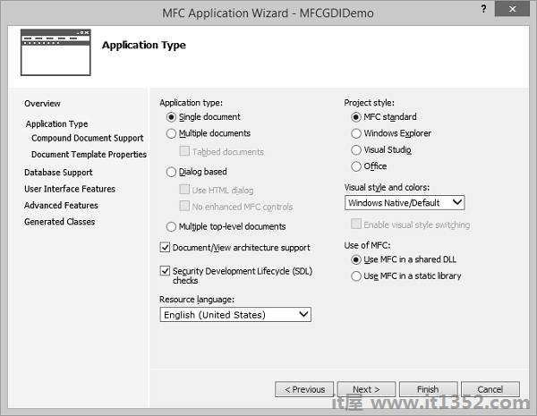
Step 2 : Once the project is created, go the Solution Explorer and double click on the MFCGDIDemoView.cpp file under the Source Files folder.
Step 3 : Draw the line as shown below in CMFCGDIDemoView::OnDraw() method.
void CMFCGDIDemoView::OnDraw(CDC* pDC) {
   pDC->MoveTo(95, 125);
   pDC->LineTo(230, 125);
   CMFCGDIDemoDoc* pDoc = GetDocument();
   ASSERT_VALID(pDoc);
   if (!pDoc)
      return;

   // TODO: add draw code for native data here
 }
Step 4 : 运行此应用程序. You will see the following output.
Step 5 : The CDC::MoveTo() method is used to set the starting position of a line.
When using LineTo(), the program starts from the MoveTo() point to the LineTo() end.
After LineTo() when you do not call MoveTo(), and call again LineTo() with other point value, the program will draw a line from the previous LineTo() to the new LineTo() point.
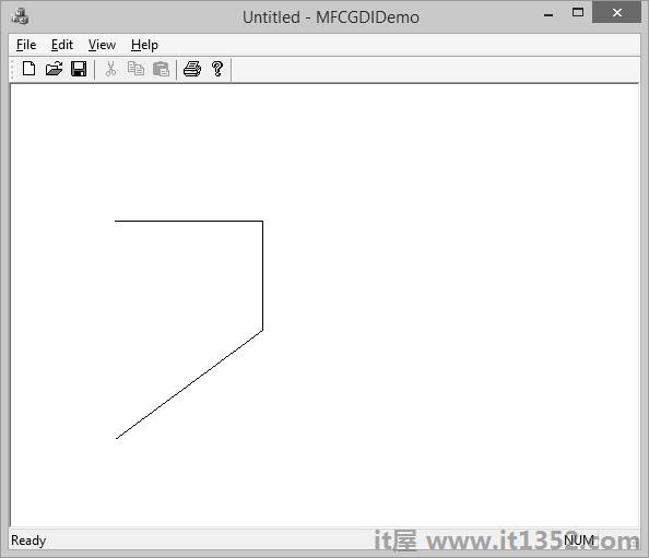
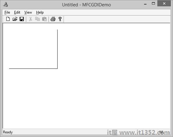
Step 6 : To draw different lines, you can use this property as shown in the following code.
void CMFCGDIDemoView::OnDraw(CDC* pDC) {
   pDC->MoveTo(95, 125);
   pDC->LineTo(230, 125);
   pDC->LineTo(230, 225);
   pDC->LineTo(95, 325);
   CMFCGDIDemoDoc* pDoc = GetDocument();
   ASSERT_VALID(pDoc);
   if (!pDoc)
      return;

   // TODO: add draw code for native data here
 }
Step 7 : 运行此应用程序. You will see the following output.
A polyline is a series of connected lines. The lines are stored in an array of POINT or CPoint values. To draw a polyline, you use the CDC::Polyline() method. To draw a polyline, at least two points are required. If you define more than two points, each line after the first would be drawn from the previous point to the next point until all points have been included.
Step 1 : Let us look into a simple example.
void CMFCGDIDemoView::OnDraw(CDC* pDC) {
   CPoint Pt[7];
   Pt[0] = CPoint(20, 150);
   Pt[1] = CPoint(180, 150);
   Pt[2] = CPoint(180, 20);
   pDC−Polyline(Pt, 3);

   CMFCGDIDemoDoc* pDoc = GetDocument();
   ASSERT_VALID(pDoc);
   if (!pDoc)
      return;

   // TODO: add draw code for native data here
 }
Step 2 : When you run this application, you will see the following output.
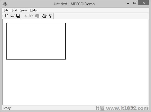
A rectangle is a geometric figure made of four sides that compose four right angles. Like the line, to draw a rectangle, you must define where it starts and where it ends. To draw a rectangle, you can use the CDC::Rectangle() method.
Step 1 : Let us look into a simple example.
void CMFCGDIDemoView::OnDraw(CDC* pDC) {
   CPoint Pt[7];
   Pt[0] = CPoint(20, 150);
   Pt[1] = CPoint(180, 150);
   Pt[2] = CPoint(180, 20);
   pDC−Polyline(Pt, 3);

   CMFCGDIDemoDoc* pDoc = GetDocument();
   ASSERT_VALID(pDoc);
   if (!pDoc)
      return;

   // TODO: add draw code for native data here
}
Step 2 : When you run this application, you will see the following output.
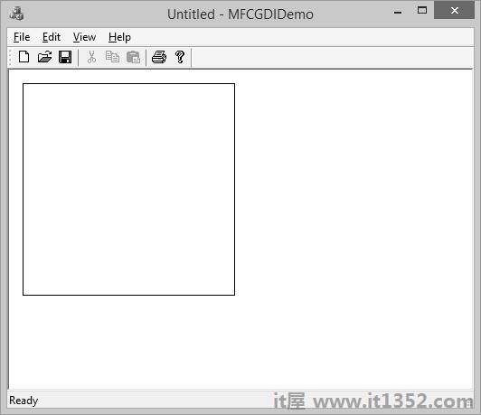
A square is a geometric figure made of four sides that compose four right angles, but each side must be equal in length.
Let us look into a simple example.
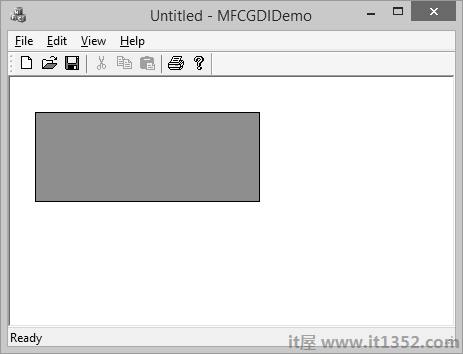
void CMFCGDIDemoView::OnDraw(CDC* pDC) {
   pDC->Rectangle(15, 15, 250, 250);

   CMFCGDIDemoDoc* pDoc = GetDocument();
   ASSERT_VALID(pDoc);
   if (!pDoc)
      return;

   // TODO: add draw code for native data here
 }
When you run this application, you will see the following output.
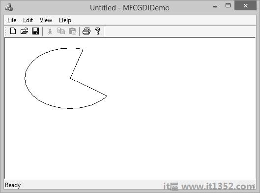
A pie is a fraction of an ellipse delimited by two lines that span from the center of the ellipse to one side each. To draw a pie, you can use the CDC::Pie() method as shown below :
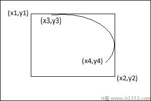
BOOL Pie(int x1, int y1, int x2, int y2, int x3, int y3, int x4, int y4);
The (x1, y1) point determines the upper-left corner of the rectangle in which the ellipse that represents the pie fits. The (x2, y2) point is the bottom-right corner of the rectangle.
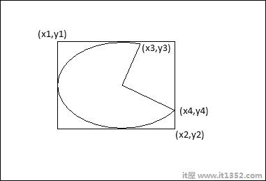
The (x3, y3) point specifies the starting corner of the pie in a default counterclockwise direction.
The (x4, y4) point species the end point of the pie.
Let us look into a simple example.
void CMFCGDIDemoView::OnDraw(CDC* pDC) {
   pDC->Pie(40, 20, 226, 144, 155, 32, 202, 115);

   CMFCGDIDemoDoc* pDoc = GetDocument();
   ASSERT_VALID(pDoc);
   if (!pDoc)
      return;

   // TODO: add draw code for native data here
 }
Step 2 : When you run this application, you will see the following output.
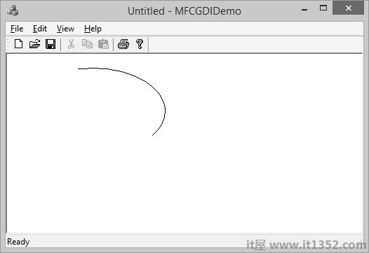
An arc is a portion or segment of an ellipse, meaning an arc is a non-complete ellipse. To draw an arc, you can use the CDC::Arc() method.
BOOL Arc(int x1, int y1, int x2, int y2, int x3, int y3, int x4, int y4);
The CDC class is equipped with the SetArcDirection() method.
Here is the syntax :
int SetArcDirection(int nArcDirection)
| Sr.No. | Value & Orientation |
|---|---|
| 1 | AD_CLOCKWISE The figure is drawn clockwise |
| 2 | AD_COUNTERCLOCKWISE The figure is drawn counterclockwise |
Step 1 : Let us look into a simple example.
void CMFCGDIDemoView::OnDraw(CDC* pDC) {
   pDC->SetArcDirection(AD_COUNTERCLOCKWISE);
   pDC->Arc(20, 20, 226, 144, 202, 115, 105, 32);

   CMFCGDIDemoDoc* pDoc = GetDocument();
   ASSERT_VALID(pDoc);
   if (!pDoc)
      return;

   // TODO: add draw code for native data here
 }
Step 2 : When you run this application, you will see the following output.
The arcs we have drawn so far are considered open figures because they are made of a line that has a beginning and an end (unlike a circle or a rectangle that do not). A chord is an arc whose two ends are connected by a straight line.
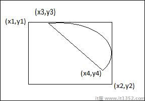
To draw a chord, you can use the CDC::Chord() method.
BOOL Chord(int x1, int y1, int x2, int y2, int x3, int y3, int x4, int y4);
Let us look into a simple example.
void CMFCGDIDemoView::OnDraw(CDC* pDC) {
   pDC->SetArcDirection(AD_CLOCKWISE);
   pDC->Chord(20, 20, 226, 144, 202, 115, 105, 32);

   CMFCGDIDemoDoc* pDoc = GetDocument();
   ASSERT_VALID(pDoc);
   if (!pDoc)
      return;

   // TODO: add draw code for native data here
 }
When you run the above application, you will see the following output.
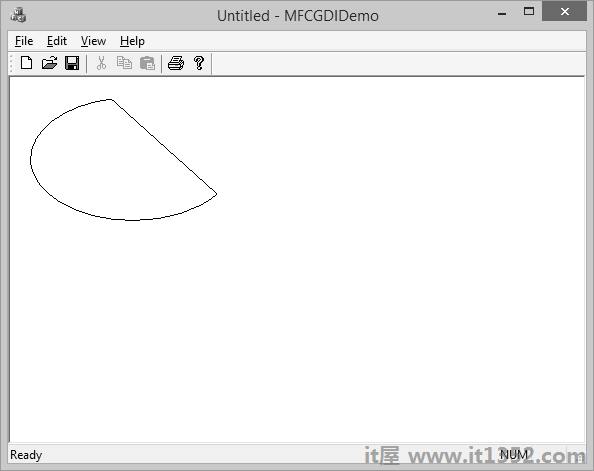
The arc direction in this example is set clockwise.
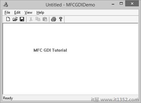
The color is one the most fundamental objects that enhances the aesthetic appearance of an object. The color is a non-spatial object that is added to an object to modify some of its visual aspects. The MFC library, combined with the Win32 API, provides various actions you can use to take advantage of the various aspects of colors.
The RGB macro behaves like a function and allows you to pass three numeric values separated by a comma. Each value must be between 0 and 255 as shown in the following code.
void CMFCGDIDemoView::OnDraw(CDC* pDC) {
   COLORREF color = RGB(239, 15, 225);
 }
Let us look into a simple example.
void CMFCGDIDemoView::OnDraw(CDC* pDC) {
   COLORREF color = RGB(239, 15, 225);
   pDC->SetTextColor(color);
   pDC->TextOut(100, 80, L"MFC GDI Tutorial", 16);

   CMFCGDIDemoDoc* pDoc = GetDocument();
   ASSERT_VALID(pDoc);
   if (!pDoc)
      return;

   // TODO: add draw code for native data here
 }
When you run this application, you will see the following output.
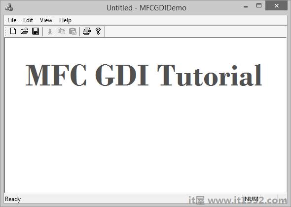
CFont encapsulates a Windows graphics device interface (GDI) font and provides member functions for manipulating the font. To use a CFont object, construct a CFont object and attach a Windows font to it, and then use the object’s member functions to manipulate the font.
| Sr.No. | Name & Description |
|---|---|
| 1 | CreateFont Initializes a CFont with the specified characteristics. |
| 2 | CreateFontIndirect Initializes a CFont object with the characteristics given in a LOGFONT structure. |
| 3 | CreatePointFont Initializes a CFont with the specified height, measured in tenths of a point, and typeface. |
| 4 | CreatePointFontIndirect Same as CreateFontIndirect except that the font height is measured in tenths of a point rather than logical units. |
| 5 | FromHandle Returns a pointer to a CFont object when given a Windows HFONT. |
| 6 | GetLogFont Fills a LOGFONT with information about the logical font attached to the CFont object. |
Let us look into a simple example.
void CMFCGDIDemoView::OnDraw(CDC* pDC) {
   CFont font;
   font.CreatePointFont(920, L"Garamond");
   CFont *pFont = pDC->SelectObject(&font);
   COLORREF color = RGB(239, 15, 225);
   pDC->SetTextColor(color);
   pDC->TextOut(100, 80, L"MFC GDI Tutorial", 16);
   pDC->SelectObject(pFont);
   font.DeleteObject();

   CMFCGDIDemoDoc* pDoc = GetDocument();
   ASSERT_VALID(pDoc);
   if (!pDoc)
   return;

   // TODO: add draw code for native data here
 }
When you run the above application, you will see the following output.
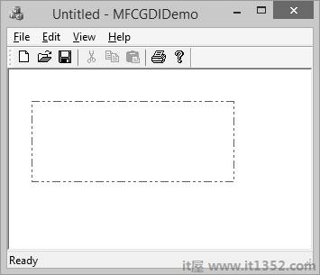
A pen is a tool used to draw lines and curves on a device context. In the graphics programming, a pen is also used to draw the borders of a geometric closed shape such as a rectangle or a polygon. Microsoft Windows considers two types of pens — cosmetic and geometric.
A pen is referred to as cosmetic when it can be used to draw only simple lines of a fixed width, less than or equal to 1 pixel. A pen is geometric when it can assume different widths and various ends. MFC provides a class CPen which encapsulates a Windows graphics device interface (GDI) pen.
| Sr.No. | Name & Description |
|---|---|
| 1 | CreatePen Creates a logical cosmetic or geometric pen with the specified style, width, and brush attributes, and attaches it to the CPen object. |
| 2 | CreatePenIndirect Creates a pen with the style, width, and color given in a LOGPEN structure, and attaches it to the CPen object. |
| 3 | FromHandle Returns a pointer to a CPen object when |
| 4 | GetExtLogPen Gets an EXTLOGPEN underlying structure. |
| 5 | GetLogPen Gets a LOGPEN underlying structure. |
| Sr.No. | Name & Description |
|---|---|
| 1 | PS_SOLID A continuous solid line. |
| 2 | PS_DASH A continuous line with dashed interruptions. |
| 3 | PS_DOT A line with a dot interruption at every other pixel. |
| 4 | PS_DASHDOT A combination of alternating dashed and dotted points. |
| 5 | PS_DASHDOTDOT A combination of dash and double dotted interruptions. |
| 6 | PS_NULL No visible line. |
| 7 | PS_INSIDEFRA ME A line drawn just inside of the border of a closed shape. |
Let us look into a simple example.
void CMFCGDIDemoView::OnDraw(CDC* pDC) {
   CPen pen;
   pen.CreatePen(PS_DASHDOTDOT, 1, RGB(160, 75, 90));
   pDC->SelectObject(&pen);
   pDC->Rectangle(25, 35, 250, 125);

   CMFCGDIDemoDoc* pDoc = GetDocument();
   ASSERT_VALID(pDoc);
   if (!pDoc)
      return;

   // TODO: add draw code for native data here
 }
When you run the above application, you will see the following output.
A brush is a drawing tool used to fill out closed shaped or the interior of lines. A brush behaves like picking up a bucket of paint and pouring it somewhere. MFC provides a class CBrush which encapsulates a Windows graphics device interface (GDI) brush.
| Sr.NO. | Name & Description |
|---|---|
| 1 | CreateBrushIndirect Initializes a brush with the style, color, and pattern specified in a LOGBRUSH structure. |
| 2 | CreateDIBPatternBrush Initializes a brush with a pattern specified by a device-independent bitmap (DIB). |
| 3 | CreateHatchBrush Initializes a brush with the specified hatched pattern and color. |
| 4 | CreatePatternBrush Initializes a brush with a pattern specified by a bitmap. |
| 5 | CreateSolidBrush Initializes a brush with the specified solid color. |
| 6 | CreateSysColorBrush Creates a brush that is the default system color. |
| 7 | FromHandle Returns a pointer to a CBrush object when given a handle to a Windows HBRUSH object. |
| 8 | GetLogBrush Gets a LOGBRUSH structure. |
Let us look into a simple example.
void CMFCGDIDemoView::OnDraw(CDC* pDC) {
   CBrush brush(RGB(100, 150, 200));
   CBrush *pBrush = pDC->SelectObject(&brush);
   pDC->Rectangle(25, 35, 250, 125);
   pDC->SelectObject(pBrush);

   CMFCGDIDemoDoc* pDoc = GetDocument();
   ASSERT_VALID(pDoc);
   if (!pDoc)
      return;

   // TODO: add draw code for native data here
 }
When you run this application, you will see the following output.